This website uses cookies so that we can provide you with the best user experience possible. Cookie information is stored in your browser and performs functions such as recognising you when you return to our website and helping our team to understand which sections of the website you find most interesting and useful.
What are the noise measurement setups available in FDCS?
FDCS supports three types of noise measurement setups; Hot-Cold Noise, Cold-In Noise and Cold-Out Noise techniques.
To create a new Noise project in FDCS, select the Create Project option from the start page or use the New Project option from the File menu.
Choose the project type as Noise and this gives the three noise measurement setups supported by FDCS.
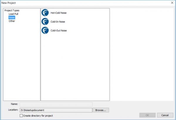
Figure 1
Hot-Cold Noise technique
This is the standard technique used for noise measurements where a noise source, connected to the input of the DUT is set to its “cold”(TC) and “hot”(TH) state, the respective noise power outputs are measured and used to calculate the noise figure of the DUT. This technique is mostly used to measure the noise figure in a 50Ω system. By inserting a tuner in between the noise source and the DUT, noise figure measurements for source impedance different than 50Ω may be performed. However, the loss of the tuner must be known with high accuracy since it enters directly into the measured noise figure value. Tuners exhibit higher loss with increasing reflection coefficient.
Select the Hot-Cold Noise option to create a new project for Hot-Cold noise measurement technique.
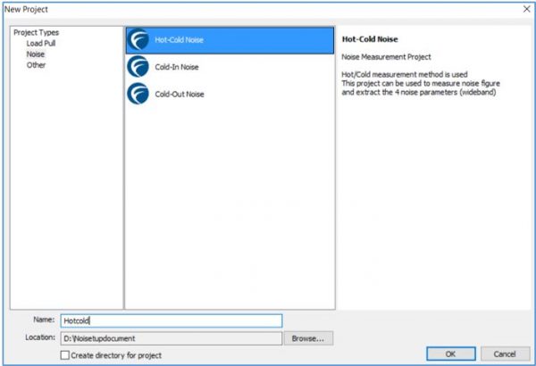
Figure 2
The measurement setup consists of input and output switch modules, a noise source connected to the input switch and the noise figure meter connected to the output switch.

Cold-In Noise technique
In the Cold-In Noise technique, the noise source is only required during the calibration phase to determine the kBG constant of the receiver. The noise figure of the DUT is calculated by knowing the source impedance, the S-parameter of the DUT and the input reflection coefficient of the receiver. This technique is most often used in automated noise parameter measurement systems.
Select the Cold-In Noise option to create a new project for Cold-In noise measurement technique.
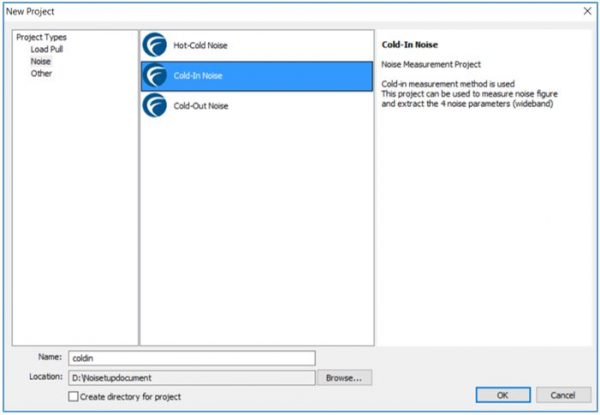
Figure 4
The measurement setup is similar to the Hot-Cold Technique and consists of input and output switch modules, a noise source connected to the input switch and noise figure meter connected to the output. However, the noise source is only used for determining the kBG constant of the receiver. The KBG and receiver cal are performed with a thru instead of the actual DUT.
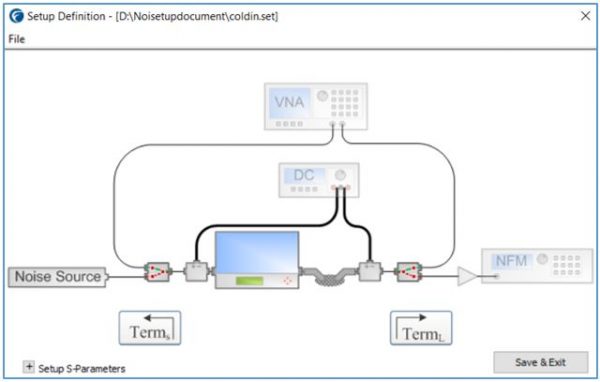
Figure 5
In the Cold-In Noise technique, the delay between the noise source and the noise figure meter can affect the measurement accuracy at very high frequencies.
Cold-Out Noise technique
In the Cold-Out Noise technique, the noise source is only required during the calibration phase, to determine the kBG constant of the receiver, similar to the Cold-In method. The noise figure of the DUT is calculated by knowing the source impedance, the S-parameter of the DUT and the input reflection coefficient of the receiver.
Select the Cold-Out Noise option to create a new project for Cold-Out noise measurement technique.
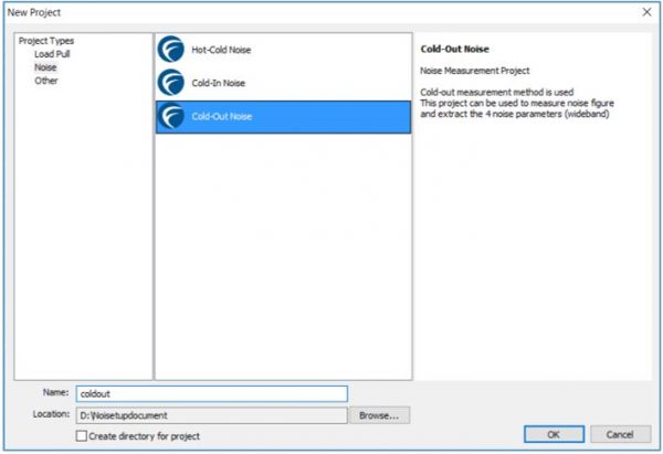
Figure 6
In the Cold-Out technique, the noise source is connected via a switch located in the output of the DUT to the noise figure meter during calibration. Thus, this technique avoids the delay issue as in the case of Cold-In method. The input tuner required to control the source impedance is connected directly to the input port of the DUT and no input switch module is used. However, a transfer switch is required at the output instead of the conventional switch.
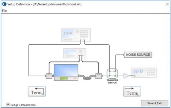
Figure 7
Additional Information:
Additional information on Focus Noise setup definitions and measurement procedure can be found in the FDCS operation manual in \Focus Microwaves\Load Pull Explorer\Manuals
Keywords: Noise measurements, Noise setup, Cold-In, Cold-Out, Hot-Cold
Last date modified: March 29, 2017