This website uses cookies so that we can provide you with the best user experience possible. Cookie information is stored in your browser and performs functions such as recognising you when you return to our website and helping our team to understand which sections of the website you find most interesting and useful.
Basic connections for the Auriga 200v system
Symptoms / Solutions:
This article presents how to connect Auriga 200V hardware.
Following items are required:
| Item | Quantity | Picture |
| Auriga AU4850 | 1 | 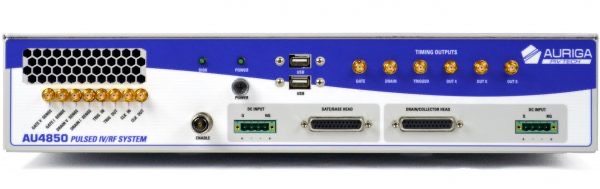 |
| Input Pulse Head | 1 | 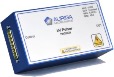 |
| Output Pulse Head | 1 |  |
| DC Supply 1 | 1 | 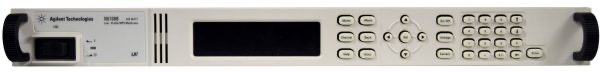 |
| DC Supply 2 | 1 | 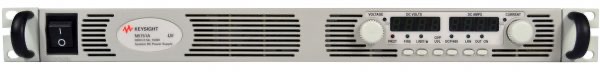 |
| Multi-meter | 1 | 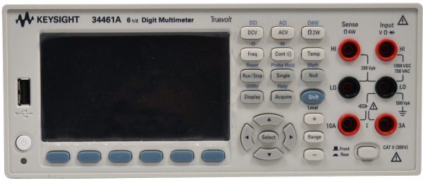 |
| Pulse Head Cable | 2 | 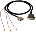 |
| SMA Timing Cable | 1 | 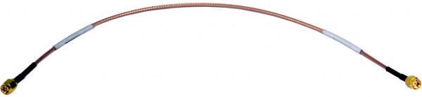 |
| DC Supply Bias Cable 1 | 1 | 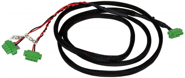 |
| DC Supply Bias Cable 2 | 1 | 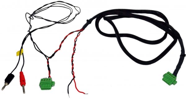 |
| USB Cable | 3 | 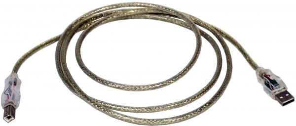 |
| Power Cable | 4 |  |
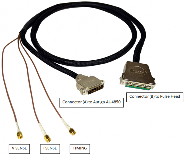
Pulser Head Cable:
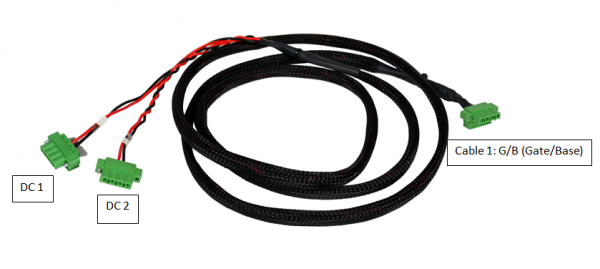
DC Supply Bias Cable 1:
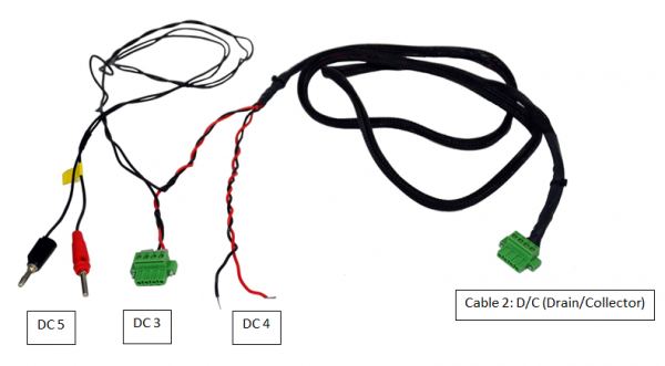
 DC Supply Bias Cable 2:
Step 1: Connect Input Pulse Head to Auriga AU4850
-
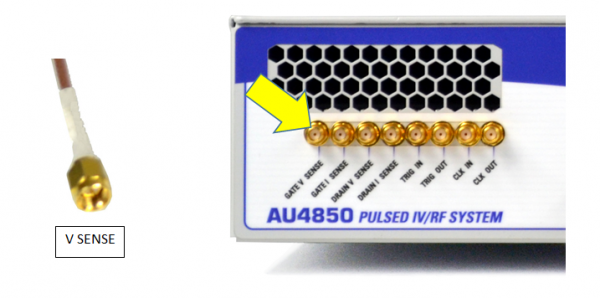
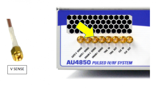
- Connect V SENSE of the Pulse Head Cable 1 to GATE V SENSE of the Auriga AU4850
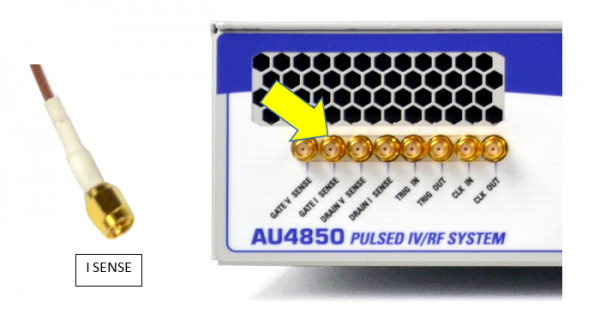
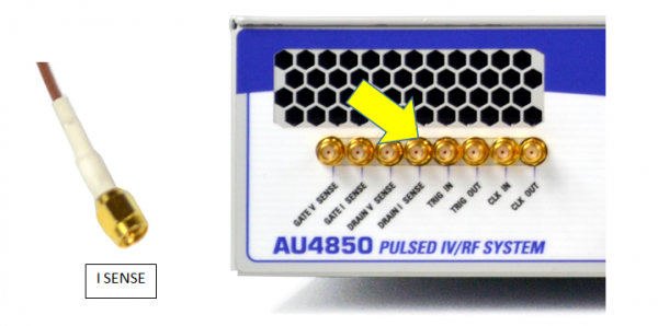
2. Connect I SENSE of the Pulse Head Cable 1 to GATE I SENSE of the Auriga AU4850
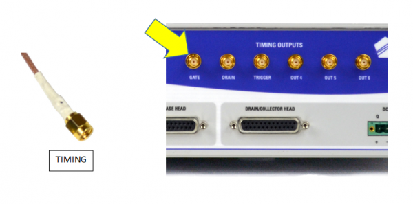
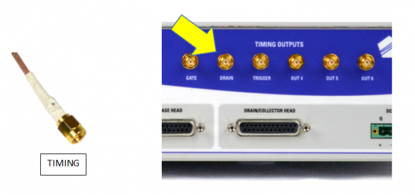
3. Connect TIMING of the Pulse Head Cable 1 to Timing Outputs GATE of the Auriga AU4850
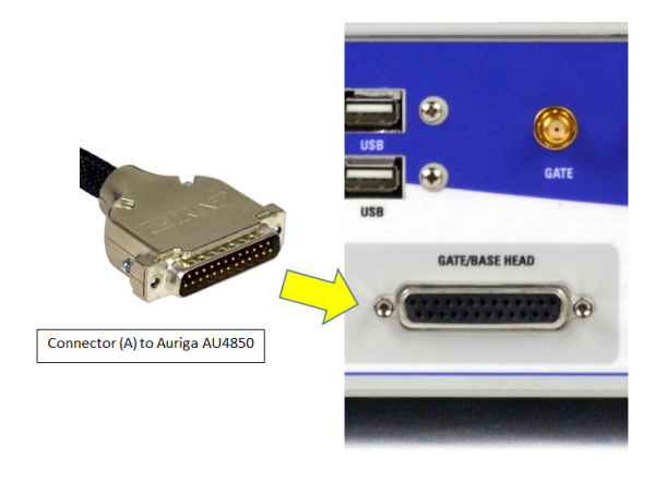
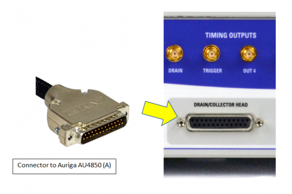
 4. Connect Connector (A) of Pulse Head Cable 1 to GATE/BASE HEAD of the Auriga AU4850
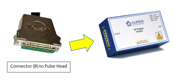
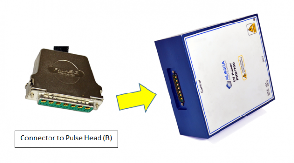
5. Connect Connector (B) of Pulse Head Cable 1 to Input Pulse Head
Step 2: Connect Output Pulse Head to Auriga AU4850
6. Connect V SENSE of the Pulse Head Cable 2 to DRAIN V SENSE of the Auriga AU4850
7. Connect I SENSE of the Pulse Head Cable 2 to DRAIN I SENSE of the Auriga AU4850
8. Connect TIMING of the Pulse Head Cable 2 to Timing Outputs DRAIN of the Auriga AU4850
9. Connect Connector (A) of Pulse Head Cable 2 to DRAIN/COLECTOR HEAD of the Auriga AU4850
10. Connect Connector (B) of Pulse Head Cable 2 to Input Pulse Head
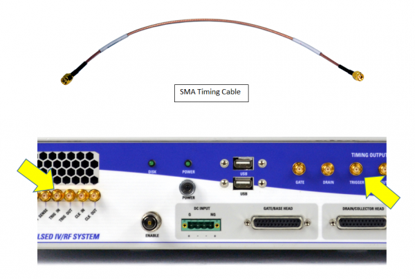
Step 3: Connect SMA Timing Cable
11. Connect one end of SMA Timing Cable to TRIG IN and the other end to Timing Outputs TRIGGER.
Step 4: Connect DC Supply Bias Cable 1
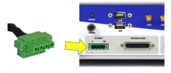
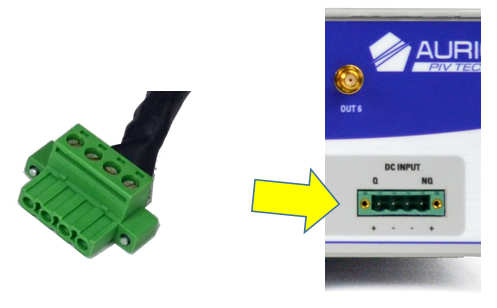
12. Connect G/B (Gate/Base) of DC Supply Bias Cable 1 to DC INPUT
13. Connect DC 1 of DC Supply Bias Cable 1 to DC Output Connector 1 at the back of the DC Supply 1.
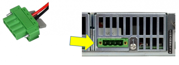
14. Connect DC 2 of DC Supply Bias Cable 1 to DC Output Connector 2 at the back of the DC Supply 1.
Step 5: Connect DC Supply Bias Cable 2
15. Connect D/C (Drain/Collector) of DC Supply Bias Cable 2 to DC Input
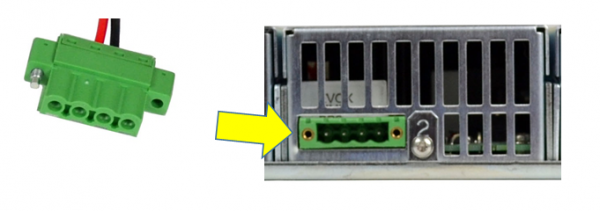
16.Connect DC 3 of DC Supply Bias Cable 2 to DC Output Connector 3 at the back of the DC Supply 1.
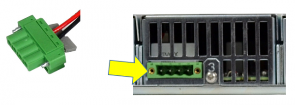
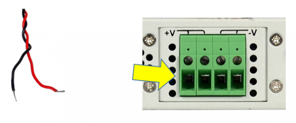
17. Connect DC 4 of DC Supply Bias Cable 2 to DC Output Connector at the back of the DC Supply 2.
- Red wire to plus (+V).
- Black wire to minus (-V)
18. Connect DC 5 of DC Supply Bias Cable 2 to 3A Current Terminal at the back of the Multi-meter.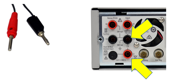
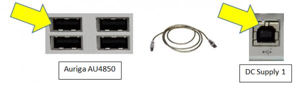
Step 6: Connect USB Cables
19. Connect Auriga AU4850 to DC Supply 1
 20. Connect Auriga AU4850 to DC Supply 2
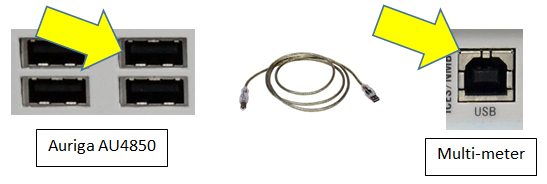
 21. Connect Auriga AU4850 to Multi-meter
Step 7: Connect Power Cables
22. Connect power cables to the instruments.
- Auriga AU4850
- DC Supply 1
- DC Supply 2
- Multi-meter