This website uses cookies so that we can provide you with the best user experience possible. Cookie information is stored in your browser and performs functions such as recognising you when you return to our website and helping our team to understand which sections of the website you find most interesting and useful.
Verification of a Noise Measurement System (Theory)
The accuracy of a noise measurement system cannot be verified in the same way as a two-tuner passive or active load pull system.
A load pull system can be verified using the Back-to-Back method (also called Delta Gt method), in which the transducer gain of a Thru Line is tested versus 0dB at all conjugate source and load tuning positions, within the dynamic range of the used power detectors.
A noise system cannot be verified against an active device, even if the noise parameters of the specific device are “known” (The “known” data cannot be fully trusted whether it be a datasheet or common knowledge).
Metrology relies only on independently verifiable standards.
Such standards are available for noise system verification but are only passive. Any passive network, comprising only thermal noise sources, can be used as noise standard. The majority of RF passive networks are such. Attenuators, filters, capacitors, inductors, resistors, T-junctions, PC boards, etc., as long as they do not include diodes, transistors, etc.
In the case of a passive component, the Noise Figure is equal to the Available Loss:
NF = 1/Gav
1/Gav has the same dependence on the source impedance as the noise figure:
1/Gav = NF = f(Γs)
Gav can easily and very accurately be calculated from the network’s s-parameters.
NF = 1/Gav = (|1-Γs*S11|2*(1-|Γo|2 )/(|S21|2 *(1-|Γs|2))
Γo = S22 + S12*S21/(1-Γs*S11)
All four Noise Parameters must check out. Differences can only be explained by limited receiver sensitivity, since passive networks lack gain. On the contrary, missing DUT Gain exacerbates the challenge on receiver calibration accuracy, which is not masked by the DUT Gain (as per Friis).
Receiver inaccuracy contributions are multiplied by the network loss instead of being divided by a DUT Gain.
Most operators will be satisfied by verifying the system using a standard attenuator. However, an accurate noise system must be also able to be verified using highly mismatched networks. The theory holds for all cases, so must the praxis.
Attached are a few examples of such verifications of a standard Focus noise measurement system. Noise tests are done twice (two-colored dots).
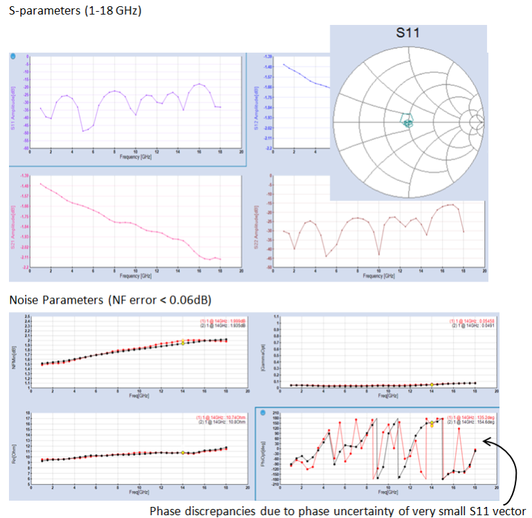
A significant element is the comparison of the randomly changing optimum phase.
Verifying a 6dB Attenuator
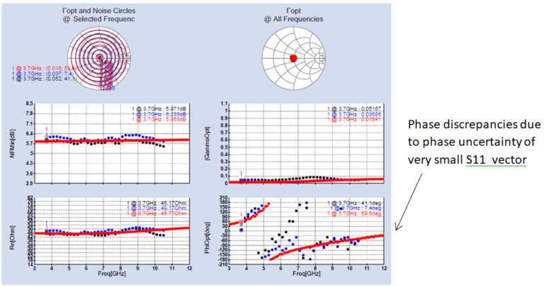
Verifying a highly mismatched PC board network
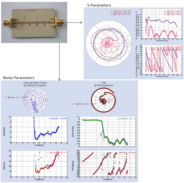
Verifying T-junction with Coaxial 2dB attenuator
Keywords: Noise measurement, NPEX, verification, FDCS
Last date modified: June 16, 2017