
This website uses cookies so that we can provide you with the best user experience possible. Cookie information is stored in your browser and performs functions such as recognising you when you return to our website and helping our team to understand which sections of the website you find most interesting and useful.
Back
Applications
Pulsed IV & S-Parameters
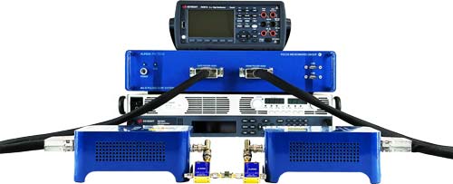
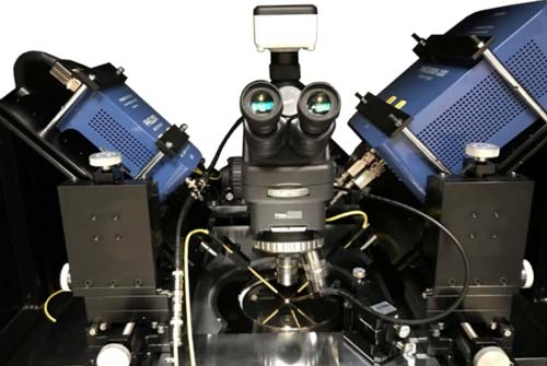
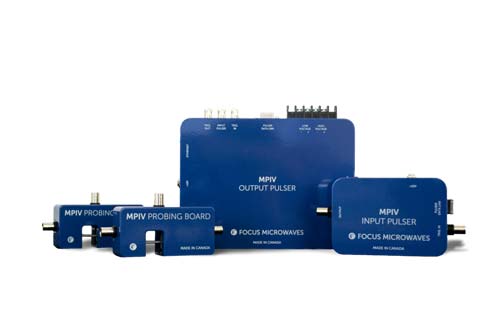
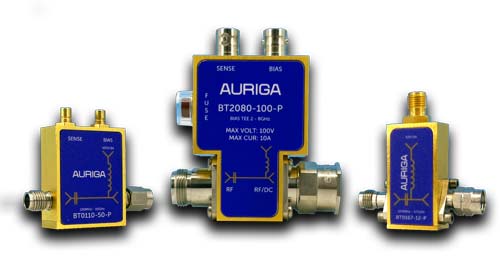
Auriga PIV system is a full featured characterization platform that can do both DC and pulsed IV characterization. The pulser head circuitry due to its low profile can be moved closer to the DUT, which helps to preserves the integrity of the pulsed signal by reducing the effects of the transmission lines on the measurements. The external pulser heads are interchangeable and available in different configurations from 20V - 100mA to 2000V - 100A.

Features
The I-V measurement is used as a tool to determine and understand the basic parameters of a device within an electronic circuit. The I-V characteristics where I-V stands for current and Voltage is the relationship between the current flowing in a circuit when voltage is applied across its terminals. Some key properties of electronic devices can be extracted from the shape and details of the curve, which enable deep insight into their operation. The IV curves are also used extensively to mathematically model the behavior of an electronic circuit.
I-V characteristics are measured for both Field Effect Transistor (FET) or Bipolar Junction Transistor (BJT). For FET the terms “Gate” and “Drain” are used while for a BJT, substitute the terms with “Base” and “Collector.”
There are two types of IV measurement methods:
- DC-IV
In DC I-V measurements a series of voltages, varied over time is applied to the device and at each voltage, the current flowing through the device is measured. This process is followed over entire measurement cycle. This continuous cycle sometimes alters the electronic properties of a device resulting from increase in temperature.
- Pulsed IV
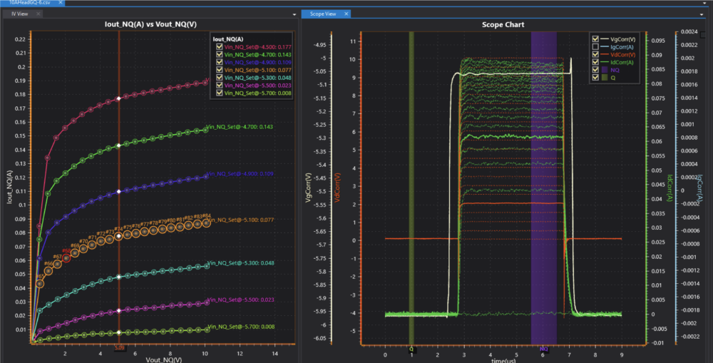
Pulsed IV characterization is similar process as implemented in DC analyses and produces similar curves for drain current when gate and drain voltage levels are stepped over time but acquired under isothermal conditions (pulsed) at a given quiescent point defined by its quiescent control voltages. This means the base of the pulses have a non-zero value for both gate and drain voltage, often referred to as the operating point or quiescent (q) point. For accurate pulsed characterization short pulse length should be used to provide IV measurements in
isothermal and isodynamic conditions. The duration of pulse period should be larger than pulse width to make sure the device should return to its steady state conditions after each measurement pulse. This eliminates self-heating and traps to some level.
- Pulsed S-Parameters
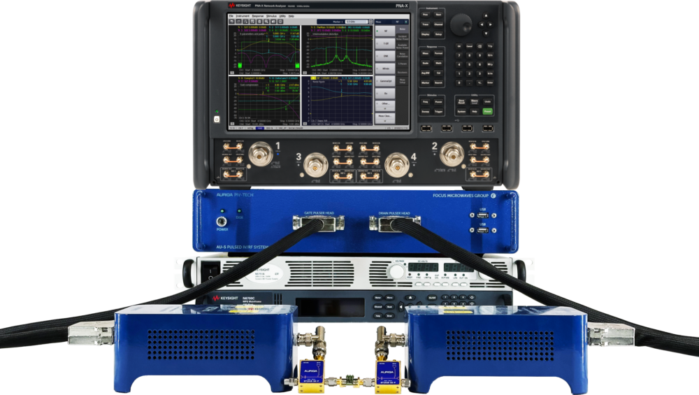
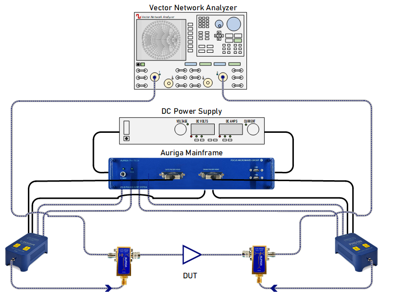
The principle of pulsed S-parameter measurements consists of superimposing the RF signal on each instantaneous bias point (VNQGate, VNQDrain) of the pulsed I-V network and perform the acquisition of S-parameters. The setup for this measurement includes pulsed I-V system that it is coupled to a vector network analyzer (VNA), that enables to pulsed S parameter measurements. The PIV system being the primary trigger module triggers the VNA. This synchronization is done to make RF measurement (S-Parameters) within the instantaneous I-V pulse. Enough delay is added in VNA to avoid RF measurements in any unstable region or the transients of IV pulse. In the measurement stage at each instantaneous point (VNQGate, VNQDrain) of the entire I-V characteristic, a S-parameter file is measured over the frequency bandwidth. Indeed, each of these S-parameter files measured in pulsed mode gives the actual response of the device at the quiescent bias point (VQGate, VQDrain).
Setup
Parameters
Setup
Parameters
The measured RF parameters include:
- PAE, ACPR
- ΓLoad, ΓIN
Request a quote
Please use this form to creating a quote.
"*" indicates required fields