

This website uses cookies so that we can provide you with the best user experience possible. Cookie information is stored in your browser and performs functions such as recognising you when you return to our website and helping our team to understand which sections of the website you find most interesting and useful.
Features
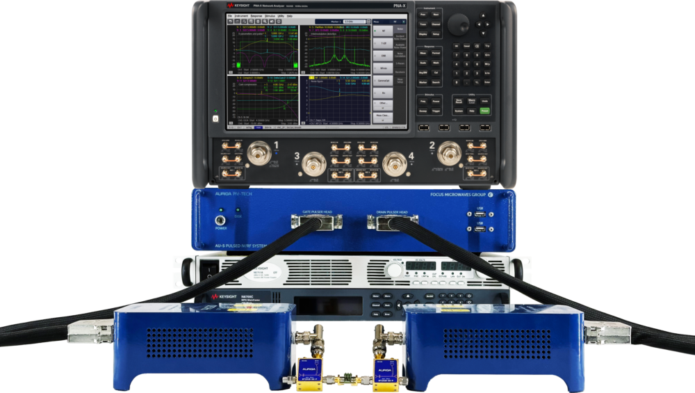
The Focus Compact Model (FCM) utility is a streamlined software package designed to be used with Focus’ AURIGA high-end Pulsed-IV system, that is used to generate Compact Models for transistors from their Pulsed-IV and wideband pulsed s-parameter data.
This is achieved by generating a network of lumped circuit elements that represent accurately the fundamental linear & non-linear behavior of the device over a broad range of bias and power range.
The result of the modeling is a netlist and compatible with- the most common CAD tools used in RF Design; such as AWR Microwave office (MWO) and Keysight PathWave Advanced Design System (ADS)
Setup
Strategy
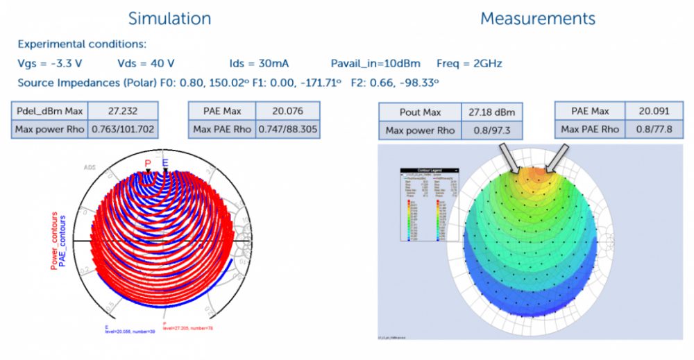
EDA Example
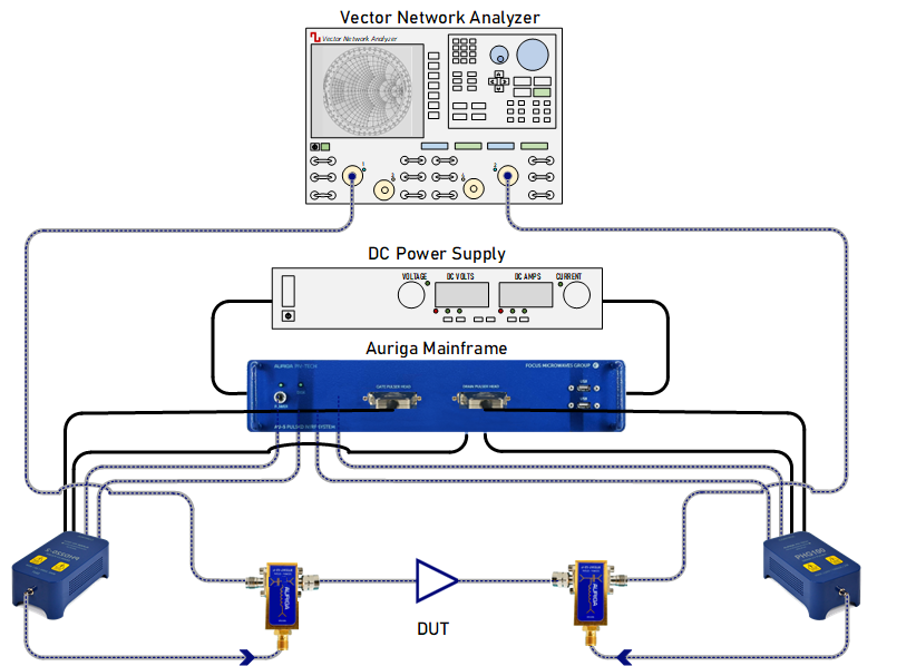
Setup
Pulsed S-Parameter Setup
The purpose of electrical representation or equivalent circuit of HEMT or any transistor in the form of lumped circuit elements is to implement and simulate its static and RF behavior in CAD tools. This technique is particularly useful and often directly correlated to physical entities within the device structure, as illustrated below.
The illustration below is a small signal topology composed of a total of 16 linear components.

This is divided into two parts:
i) The Intrinsic part where the region under the gate (modulation occurs here) represented with a set of 8 intrinsic elements (RGD, Ri, CGS, CGD, CDS, GM, RDS, Τ).
ii) The Extrinsic part represented with a set of 8 extrinsic elements (RG, RD, RS, LG, LD, LS, CPG, CPD). These elements need to be extracted for small signal model implementation. The extraction process will be discussed in the following section.
Strategy
Model Generation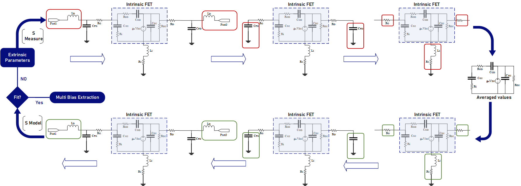
EDA Example
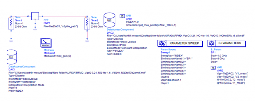
Example Measurement Export to CAD – Keysight ADS

Example Model Export to CAD
- ADS Schematic
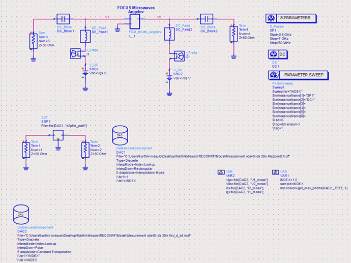
- Focus Compact Model

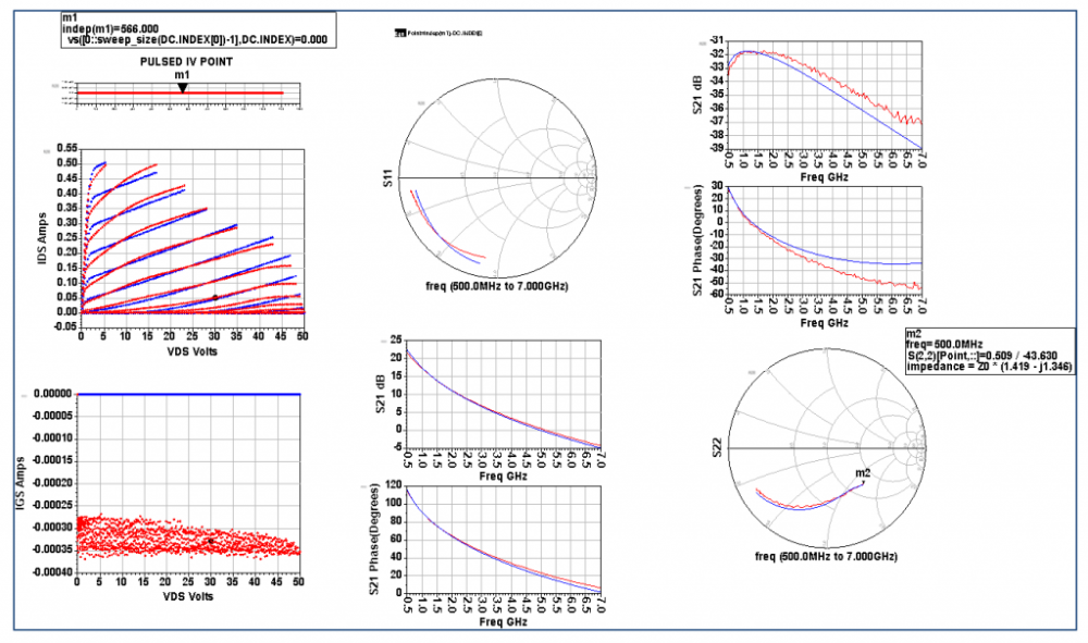
- ADS Data Display
Request a quote
Please use this form to creating a quote.
"*" indicates required fields